
Back to Brunswick Instrument home page
WE HAVE MOVED. CLICK ABOVE FOR
DETAILS
The dial indicating chamfer diameter gage has been a staple inspection tool in many machine
shops for decades now. The hand held gages quickly determine the top diameter of tapered or chamfered holes,
countersinks, female centers, valve seats, etc., with a high degree of accuracy and repeatability. Unlike
micrometers, calipers, simple indicators and other common precision tools that perform their measurements
in an obvious and easily observed manner, the chamfer diameter gage has always seemed to leave many users
scratching their heads. The following should completely demystify these useful tools.
How does this gage measure diameter?
Although we may call it a "chamfer" gage or a "countersink" gage, in all cases it is in fact a "depth" gage.
Regardless of brand or trade name, every gage of this type simply measures the depth that a cone shaped
member (called the gage "plunger") has fallen into a hole, where it comes to a stop, gently wedged in place.
There is always a direct linear relationship between the distance that the conical plunger travels into the
part and the diameter on the part taper at which it comes to rest. The gage incorporates a base plate, through
which the plunger passes, that is pressed against the face of the part above the taper and provides a plane
from which the depth measurements are referenced. The most common gages have a 90o included angle on the gage
plunger resulting in a 2:1 ratio between the taper diameter observed and the dial indicator rack travel.
Another popular version has an included angle near 127o resulting in a 4:1 diameter to depth ratio. Choosing
which to use depends on the nature of your parts.
Do I need a gage having a plunger angle that matches the part angle?
If the part angle just needs to be less than the gage angle why can't I use a 127o model
on 60o countersink?
You can. In the real world however we find that the sharper, pointier angle on the 90o gage provides a firmer,
more positive feel when inserting the gage in the part. Flatter angle gage plungers tend to "swim" around a
bit more in the hole. Also, the 90o gages are half as sensitive due to the lower diameter:depth conversion
ratio and therefore can be rated twice as accurate. Brunswick Instrument's DIALSINK brand gage accuracy for
example is rated as +/-.001" for 90o models over a 1" diameter range and +/-.002" for the 127o models. If
most of your tapered hole work falls in the 90o and under category, the 90o gage models are a much better
choice. If you make 100o countersunk holes all day, you have no choice but a gage with a larger plunger
angle.
Yes. The special gearing and/or special dial face on these indicators performs the conversion of depth to a
diameter measurement. The 2:1, 4:1 or other conversion ratio is built into the indicator. Also the direction
of the graduations is reversed from that of a "normal" indicator. As the plunger on a chamfer diameter gage
is pressed inward, the readings get smaller. Just the opposite of what's typical.
What about digital electronic indicators for these gages?
For a long time, because of the non-standard conversion ratios involved, typical electronic dial indicators had
not been usable on these gages. Only recently have truly digital indicators become available that are capable
of having special conversion ratios programmed into them. All the popular chamfer and countersink diameter gages
are now available with digital electronic readouts and offer a variety of SPC data output formats. Existing
mechanical gages can be upgraded with new digital indicators.
Will radiused edges at the top of the part taper effect the gage reading?
Any special considerations for measuring 60o machine centers?
Yes. Typically 60o female centers machined into the ends of shaft-like parts are there for subsequent "between
centers" type turning or grinding operations. Their size is important for controlling the lateral position
of the part in the machine, which affects shoulder to shoulder positions, lengths and such. Although measuring
to control the top diameter of the center would seem like the right thing to do there might be a better choice.
First, many centerdrilled holes are additionally spot-faced or otherwise interfere with accurate results using
a chamfer diameter gage. Second, the gage can't tell if the angle of the hole is off which will affect how the
hole accepts a machine center. What you really want to know is: How far will a 60o machine center go into this
hole? We recommend the use of a specially adapted version of the gage that has a 60o plunger that duplicates
the way in which an actual machine center will seat in the part. Typically, these gages measure depth rather
than diameter because 60o geometry doesn't result in a convenient diameter:depth conversion ratio.
How are these gages calibrated?
When building new gages or re-calibrating customer units, Brunswick Instrument inspects the calibration of a typical
gage at nine different diameters using nine different master rings spanning practically the entire 1" measuring
range of the instrument. It's not possible to adjust one point in the measuring range without shifting all the
other points by similar amounts. The use of many rings simply offers a quick way of verifying that accuracy exists
throughout the entire measuring range. For customer calibration we would recommend a single ring sized near the
center of the gage measuring range or a pair of rings sized somewhat in both directions from the center of the range.
A single .500" ring or a pair, .250" and .750" in diameter, would be typical for a 0-1" range gage. If a gage is
constantly used for a particular chamfer or countersink diameter we would recommend having a setting ring of the
same nominal part size for calibration.
How are the setting rings calibrated?
What's the "SET TO" number stamped on the back of the indicator?
Most chamfer diameter gages give the user a way of quickly verifying the calibration setting without using a ring
gage or other setting standard. After a new gage is assembled and calibrated the gage maker presses it against a
flat, ground surface and observes the reading on the dial. Although the gage is not actually measuring diameter
of a hole, the reading is a repeatable reference that can be easily duplicated by anyone with a flat surface handy,
like a granite surface plate. This number is assigned to the gage as its "SET TO" number and stamped on the back of
the indicator. Whenever the user wishes to check the setting of the gage, it is simply again pressed against a
flat surface and the dial of the indicator adjusted to read the "SET TO" number. The "SET TO" number actually
corresponds to the diameter of the flat area on the end of the gage plunger. On gage models with measuring range
down to "zero" (never actually all the way down to zero), the tiny flat on the plunger tip has a diameter equal
to the "SET TO" number and is actually the minimum diameter measurable by the gage. Over time, with constant use,
this small tip flat can become worn, usually somewhat rounded off and larger. The "SET TO" number can no longer
be relied upon under these conditions and the gage should be re-calibrated with rings and a new "SET TO" number
established. Larger capacity gages, having much larger flat areas on the end of the plunger, have little problem
with "SET TO" numbers changing over time.
Properly applied, properly maintained and properly calibrated, chamfer and countersink diameter gages will provide
years of fast, accurate tapered hole inspection.
Chamfer Gages & Countersink Gages Demystified -
Dialsink Gages - Measuring Chamfers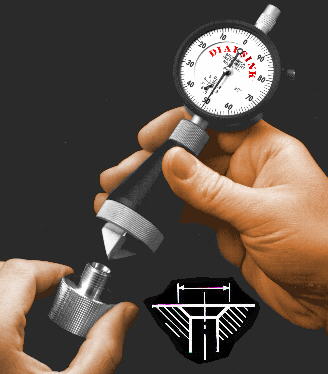
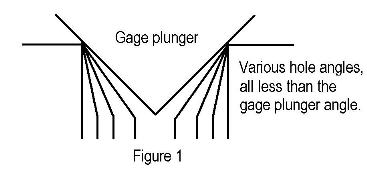 The gage plunger needs only to contact the top edge of the part taper, at the face of the part. Figure #1
illustrates that the gage plunger will contact only the top edge of any tapered hole having an included angle
less than that of the gage plunger. On any of the various part angles shown, the plunger always falls to the
same depth and the gage will register the same diameter reading. Figure #2 illustrates the problem that occurs
when the included angle of the part is greater than that of the gage plunger. In this case the gage will
erroneously register a diameter reading much smaller than it should.
The gage plunger needs only to contact the top edge of the part taper, at the face of the part. Figure #1
illustrates that the gage plunger will contact only the top edge of any tapered hole having an included angle
less than that of the gage plunger. On any of the various part angles shown, the plunger always falls to the
same depth and the gage will register the same diameter reading. Figure #2 illustrates the problem that occurs
when the included angle of the part is greater than that of the gage plunger. In this case the gage will
erroneously register a diameter reading much smaller than it should.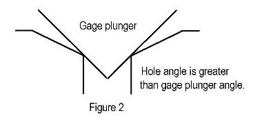 Is there anything special about the dial indicators on these gages?
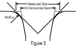 Yes, this is a problem that has to be analyzed. Figure #3 illustrates the measurement error that occurs when
a radius (or another chamfer) is present at the top end of the part taper. Choosing a gage plunger angle
that is as close to the part taper angle as possible minimizes the error. Radiuses on a typical 90o
countersink when using a 90o gage won't produce any error at all. Gages can be built with angles that
exactly match the part taper when this condition is especially problematic.
Yes, this is a problem that has to be analyzed. Figure #3 illustrates the measurement error that occurs when
a radius (or another chamfer) is present at the top end of the part taper. Choosing a gage plunger angle
that is as close to the part taper angle as possible minimizes the error. Radiuses on a typical 90o
countersink when using a 90o gage won't produce any error at all. Gages can be built with angles that
exactly match the part taper when this condition is especially problematic. The easiest method to accurately calibrate or verify calibration of a chamfer diameter gage is with a plain ring
gage having sharp edges at the bore openings as illustrated in Figure #4. As long as the bore edges are sharp,
the ring gage bore diameter can be relied upon as a setting standard for chamfer and countersink type gages.
Plain rings produced for traditional go/no-go O.D. inspection purposes all have a radius or chamfer intentionally
machined at the bore openings to aid in guiding the ring over a cylindrical part, and must not be used. Brunswick
Instrument and others will supply rings prepared with the proper sharp edges for accurate calibration results.
Existing standard plain rings of known size can be surface ground with little difficulty to remove the radius or
chamfer as long as a sharp, burr free edge can be produced. Over time, with constant use, the sharp edges on a
setting ring can break down effectively making the top diameter of the bore larger. Simple surface grinding will
again re-sharpen the edges and make the ring as accurate as when new.
The easiest method to accurately calibrate or verify calibration of a chamfer diameter gage is with a plain ring
gage having sharp edges at the bore openings as illustrated in Figure #4. As long as the bore edges are sharp,
the ring gage bore diameter can be relied upon as a setting standard for chamfer and countersink type gages.
Plain rings produced for traditional go/no-go O.D. inspection purposes all have a radius or chamfer intentionally
machined at the bore openings to aid in guiding the ring over a cylindrical part, and must not be used. Brunswick
Instrument and others will supply rings prepared with the proper sharp edges for accurate calibration results.
Existing standard plain rings of known size can be surface ground with little difficulty to remove the radius or
chamfer as long as a sharp, burr free edge can be produced. Over time, with constant use, the sharp edges on a
setting ring can break down effectively making the top diameter of the bore larger. Simple surface grinding will
again re-sharpen the edges and make the ring as accurate as when new.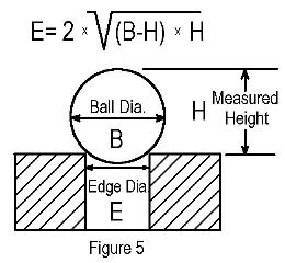 Because we are only concerned with the actual diameter at the extreme top edge of the ring gage bore, a bore gage,
which does a nice job of measuring the bore size down inside the ring, cannot be used. Figure #5 illustrates a
method of measuring gage ball height to accurately determine the bore's top diameter. Although any ball larger
in diameter than the ring bore could be used, its best to choose a ball with diameter around 1.5 times the diameter
of the ring bore. This way the ball will contact the ring bore at the top edge of the small chamfer typically
worn on it. The mathematic formula in Figure #5 will calculate the ring edge diameter from the measured ball
height.
Because we are only concerned with the actual diameter at the extreme top edge of the ring gage bore, a bore gage,
which does a nice job of measuring the bore size down inside the ring, cannot be used. Figure #5 illustrates a
method of measuring gage ball height to accurately determine the bore's top diameter. Although any ball larger
in diameter than the ring bore could be used, its best to choose a ball with diameter around 1.5 times the diameter
of the ring bore. This way the ball will contact the ring bore at the top edge of the small chamfer typically
worn on it. The mathematic formula in Figure #5 will calculate the ring edge diameter from the measured ball
height.Click for: Dialsink Gage Models and Specifications
Click for: Countersinking Handbook
Contact us with your
requirements by phone, fax or email.


Brunswick Instrument, LLC
21535 County Hwy. X
Kiel, WI 53042
Tel: (920) 894-1176
Fax:(920) 894-1162
E-Mail: info@brunswickinstrument.com