
Back to Brunswick Instrument home page
WE HAVE MOVED. CLICK ABOVE FOR
DETAILS
Click
for our selection of Film Thickness Thickness measurement of thin, soft materials such as poly films, magnetic tape or disk substrates, and metal foils
poses several unique problems. Most direct thickness measurement techniques have been afflicted by inadequate
sensitivity and non-repeatability. Rather than fighting with poor measurement systems many producers have adopted
indirect methods, such as weighing certain quantities of product, in an effort to control overall batch thickness.
Unfortunately, problems of uniformity from spot to spot on a product can not be identified in this manner.
Specialized equipment and methods are required to achieve high accuracy, repeatable thickness measurements.
Resolution
The first requirement for any serious system is very fine measurement resolution. Typical micrometers or dial
indicators reading in one-ten-thousandth of an inch (.0001") or even fifty millionths (.00005") increments are
simply not sensitive enough.
Consider that a product like common video tape may have an overall thickness of about .00075". Regardless of the
engineering or production tolerance for the product, a variation of .0001" in thickness represents material
CONSUMPTION variation of about 10 to 15 percent. Perceived variation of .0001" or more, when there actually
is none, could easily be attributed to inadequate instrument resolution. If the measurement system indicates
that process adjustments are necessary, when in fact they are not, things get even more out of control. Assuming
that the production equipment is capable, tremendous material savings are possible with more accurate measurements.
Measurement resolution of ten millionths of an inch (.00001") is a good choice for measuring films and foils.
Any system more sensitive than this will suffer in repeatability on soft materials and must be used in only the
most carefully controlled environments. Even .00001" resolution will require considerable attention to cleanliness
on the inspector's part. An electronic "gage amplifier" is best suited for the job.
Amplifiers
An electronic gage amplifier, or electronic "comparator" as it may be called, is a specialized voltmeter device with
a digital or meter style display that receives signals from a remote gage probe or "gage head". A gage amplifier
offers the best combination of ruggedness and value in a device capable of delivering the required measurement
resolution.
A digital model should be chosen that can provide .00001" resolution while simultaneously having measuring range
of at least .020" to accommodate a wide variety of material thicknesses. Models with meter style analog displays
do not have this capability and should be avoided for this application. Typical gage amplifiers also allow
measurement data to be electronically transmitted for computerized SPC or other data acquisition applications.
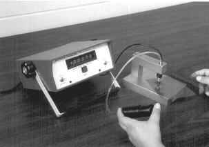
Setup
The probe is technically described as an L.V.D.T. (linear, variable, differential transformer) transducer.
The probe is cylindrical, usually 3/8" in diameter and several inches long. It has a spring loaded plunger at
one end and an electrical cable exiting at the other. It usually is probe is mounted in a gage stand, above a
smooth flat surface or "anvil", and contacts the material placed under the probe tip similarly to a typical
dial indicator setup. The amplifier is set to read "zero" when no material is present and will read the material
thickness directly when it is placed under the probe. The entire setup is easily calibrated using standard
N.I.S.T. traceable gage blocks. The mechanical considerations of gaging film are essential for accurate measurements
and reliable gage performance.
Pressure
Gaging pressure is usually not of concern when measuring common materials because they are relatively incompressible.
Films and foils, however, are soft, making gaging pressure a variable to be considered. The gage setup must balance
gaging pressure - low enough not to compress the material and high enough to provide good repeatability. It would
seem the probe plunger spring is the controlling element of the gaging pressure. But in reality, the shape and
alignment of the probe tip have a greater effect on the pressure applied to the test sample. Probe tips screw on
and off of the probe plunger and are interchangeable with any of the tips commonly available for dial indicators.
Tips having spherical or pointed shapes are not usable for measuring films and foils because they penetrate the
soft material very easily. Flat surfaced tips contact the sample over a wider area, distributing the force and
reducing the pressure applied to any one point.
Alignment
Once a tip is chosen, alignment comes into play. If the face of the flat contact tip is not parallel to the flat
anvil below it, a single point contact occurs at the edge of the tip flat. The tip begins to penetrate into the
material making the material measure thinner than it actually is. Even slight misalignment can produce readings 5
percent lower than actual. With interchangeable tips, probes and adjustable gage stands all being mass produced
by various vendors, it just is not possible to assemble a properly aligned gaging system out of the box without
some additional steps.
Once assembled, the gage probe tip and gage stand anvil can be mated to one another reasonably well with a hand
"lapping" operation. With the probe tip sprung against the anvil in its normal "zero" position, a small piece
of aluminum oxide lapping paper (not cloth), of 400 to 600 grade grit, can be placed under the tip. With the
abrasive side of the paper against the tip (NOT THE ANVIL) the paper is carefully held flat against the anvil
and moved with small circular motions until the tip has been lightly sanded into a mated position. This operation
shouldn't take more than a minute or two and must be performed whenever probe tips are changed or when the probe
is removed and reinstalled into the stand. Be sure that the probe tip used is made of hardened steel and not carbide.
Attempts to hand lap a tungsten carbide tip in this manner will be fruitless.
After lapping, moving a clean piece a paper around under the probe will remove any grit or residue. It is not
at all uncommon to find previously undersize readings of .00190" on a 2 mil film product climbing to over
.00200" and passing inspection after performing this simple operation.
The size of the flat area of the tip is another variable in the measurement system. It would again seem logical
that the larger area that the probe pressure can be spread across, the less compression of the material that will
occur. True, but again the parallel alignment of tip and anvil will do far more to prevent tip penetration than
will increasing the tip size. An improperly aligned large tip is just as bad as an improperly aligned small one.
When properly aligned, one is little different than the other.
A good overall tip design for films and foils is one with a 1/4" diameter flat tapering or curving to a 3/4" overall
diameter. The design allows the probe tip to be lifted easily with a finger under the edge and also eliminates
sharp edges around the flat that may snag material.
In an effort to eliminate the problems associated with gage stand and tip alignment, Brunswick Instrument has
developed a stand specifically designed for the measurement of thin films and foil products. The main departure
from conventional designs is the incorporation of a "floating" anvil surface in the new TMS-1 stand. The probe
is held rigidly in an arm extending out over a special flat anvil approximately 1/2" in diameter. The anvil
"floats" on a special spherical swivel mount and is flush with the surrounding surface of the stand base. Each
time the probe tip exerts pressure against the anvil, the anvil aligns itself against the tip. Tests show that the
TMS-1 provides the same accuracy as properly aligned and lapped rigid-anvil setups.
 Measurement Systems

 |
Brunswick Instrument, LLC 21535 County Hwy. X Kiel, WI 53042 Tel:  (920) 894-1176 (920) 894-1176Fax: (920) 894-1162E-Mail: info@brunswickinstrument.com |